


Use VCE Exam Simulator to open VCE files
This Chapter covers following Topic Lessons
This Chapter covers following Lab Exercises
In this chapter we will add GatewaySubnet to Virtual Network VNETCloud. We will create Virtual Network Gateway in GatewaySubnet.
We will also add GatewaySubnet to Virtual Network VNETOnPrem. We will create Virtual Network Gateway in GatewaySubnet.
We will connect VNETCloud and VNETOnPrem using S2S VPN.
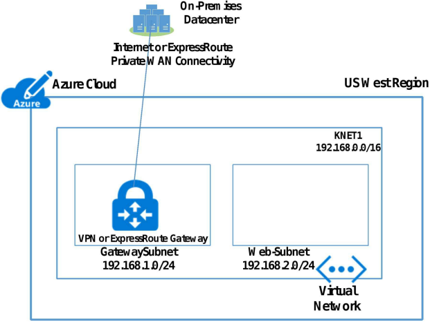
You can connect Virtual Network to on-premises Datacenter through virtual network gateway located in GatewaySubnet using either Internet VPN (P2S or S2S VPN) or ExpressRoute Private WAN connectivity.
For Internet VPN you deploy virtual network gateway of type VPN. For Private WAN connectivity you deploy virtual network gateway of type ExpressRoute.
Figure below shows Virtual Network Connected to on-premises Datacenter.
Every Azure VPN gateway consists of two instances in an active-standby or active-active configuration.
Note: ExpressRoute will be discussed in Chapter 13.
You can connect Virtual Network (VNET) to your on-premises networks over public internet using Azure VPN Gateway. A VPN gateway is a type of virtual network gateway that sends encrypted traffic across a public connection. The connectivity uses the industry-standard protocols Internet Protocol Security (IPsec) and Internet Key Exchange (IKE).
VPN gateway connects VNET to on-premises network using Site to Site VPN (S2S) or Point to Site VPN (P2S). S2S VPN uses VPN device onpremises. P2S VPN uses VPN client software on client computers in on premises infrastructure.
VPN Gateway is created in GatewaySubnet. A GatewaySubnet is created in Azure Virtual Network (VNET).
Figure below shows Virtual Network Connected to on-premises Datacenter.
Every Azure VPN gateway consists of two instances in an active-standby configuration.
VPN gateway supports following 2 type of VPN. VPN Types are selected when you are creating Virtual Network gateway of type VPN.
PolicyBased: PolicyBased VPNs were previously called static routing gateways. Policy-based VPNs encrypt and direct packets through IPsec tunnels based on the IPsec policies configured with the combinations of address prefixes between your on-premises network and the Azure VNet.
RouteBased: RouteBased VPNs were previously called dynamic routing gateways. RouteBased VPNs use "routes" in the IP forwarding or routing table to direct packets into their corresponding tunnel interfaces. The tunnel interfaces then encrypt or decrypt the packets in and out of the tunnels.
Table below shows comparison between Route-Based and Policy Based VPN.
VPN gateway comes in following 4 Editions or SKUs.
A Site-to-Site (S2S) VPN gateway connects Virtual Network (VNET) to on premises infrastructure over IPsec/IKE VPN tunnel. This type of connection requires a VPN device located on-premises that has public IP address assigned to it and is not located behind a NAT.
Site to Site VPN can also be used to connect VNET to VNET.
Figure below shows VNET to on-premises connectivity. A VPN Device is required on-premises with Public IP (Not shown in below Figure).
Figure below Shows VNET to on-premises Connectivity (Multisite).
Figure below shows VNET to VNET connectivity.
A Point-to-Site (P2S) VPN gateway creates a secure connection between virtual network and on-premises using VPN client software installed on individual client computers. P2S is a VPN connection over SSTP (Secure Socket Tunneling Protocol). P2S connections do not require a VPN device or a public-facing IP address to work.
In this exercise we will Connect Virtual Networks VNETCloud & VNETOnPrem using S2S VPN. VNETCloud & VNETOnPrem were created in Exercise 3 and 6.
Step 1 Create GatewaySubnet in Virtual Network VNETCloud
In Virtual Network VNETCloud Dashboard Click Subnets in left pane> Subnet blade opens as shown below.
In right pane Click +GatewaySubnet> Add Subnet blade opens> In Address Range enter 10.1.7.0/24. Select none for Route table & Subnet Delegation & 0 for Service Endpoints>Click Ok (Not Shown).
Step 2 Create Virtual Network Gateway in GatewaySubnet of VNETCloud
Click Create a resource>Networking>Virtual Network gateway> Create virtual network gateway blade opens>Enter a name, Select Location EAST US 2, Select gateway type as VPN, VPN type as route based, Select SKU VpnGw1, Select VNETCloud and Select Create new Public IP and enter a name> Make sure active- active mode and BGP option are disabled>Click Review +create (Not Shown)>After validation is passed click create.
Figure below shows Dashboard of Virtual Network gateway VPNCloud.
Step 3 Create GatewaySubnet in Virtual Network VNETOnPrem
In Virtual Network VNETCloudOnPrem Dashboard Click Subnets in left pane> Subnet blade opens as shown below.
In right pane Click +GatewaySubnet> Add Subnet blade opens> In Address Range enter 192.168.7.0/24. Select none for Route table & Subnet Delegation & 0 for Service Endpoints>Click Ok (Not Shown).
Step 4 Create Virtual Network Gateway in GatewaySubnet of VNETOnPrem
Click Create a resource>Networking>Virtual Network gateway> Create virtual network gateway blade opens>Enter a name, Select Location West US 2, Select gateway type as VPN, VPN type as route based, Select SKU VpnGw1, Select VNETOnPrem and Select Create new Public IP and enter a name> Make sure active- active mode and BGP option are disabled>Click Review +create (Not Shown)>After validation is passed click create.
Figure below shows Dashboard of Virtual Network Gateway VPNOnPrem
Step 3 Create Virtual Network VNETCloud Gateway Connection
Go to Virtual Network gateway VPNCloud Dashboard>Click Connections in left pane> In Right pane Click +Add> Add Connection Blade opens>Enter a name> In Connection type select VNet-to-VNet> First VNG should be VPNCloud, Second VNG should be VPNOnPrem, Enter a shared key 123xyz>Make sure Resource Group is RGCloud> Click Ok. Note : S hared key must be same on both sides.
Step 4 Create Virtual Network VNETOnPrem Gateway Connection
Go to Virtual Network gateway VPNOnPrem Dashboard>Click Connections in left pane> In Right pane Click +Add> Add Connection Blade opens>Enter a name> In Connection type select VNet-to-VNet> First VNG should be VPNOnPrem, Second VNG should be VPNCloud, Enter a shared key 123xyz>Make sure Resource Group is RGOnPrem> Click Ok. Note : S hared key must be same on both sides.
Step 5 Checking the Connections Created and flow of Data
Do this exercise after 5 minutes of previous exercise.
Go to either Virtual Network Gateway VPNCloud or VPNOnPrem Dashboard> Click Connections in left pane> It will show both the connection with status Connected. If not then wait till it shows. If required refresh the screen with F5.
RDP to VM VMFE1> Open Command Prompt and Ping Private IP of VMAD. It was successful.
Click one of the connection. You can see Data in and Data Out.
This is a demonstration exercise to Connect Virtual Network VNETCloud to On-Prem VPN Device. We will use the Virtual Network Gateway VPNCloud created in Previous Exercise. We will assume Public IP Assigned to On-Prem VPN device is 128.8.8.8. Address range of On-Prem Network located behind public IP is 10.101.0.0/24.
Below is the topology for this Exercise.
In this we add one more step which is creating Local Network Gateway. Local network gateway refers to your on-premises location.
Following are the steps for this exercise.
Step 3: Create Local Network Gateway
Local network gateway refers to your on-premises location. We need to specify the IP address of the on-premises VPN device to which we will create a connection. We also need to specify the IP address prefixes. The address prefixes you specify are the prefixes located on your on-premises network.
Click Create a resource> In the search box, type Local network gateway, then press Enter to search. This will return a list of results. Click Local network gateway and then click the Create button to open the Create local network gateway Blade>Enter name>Enter Public IP of VPN Device and select IP Addresses of on-premises network >Select RG RGCloud>Click Create.
Figure below shows the dashboard of Local Network Gateway LNGCloud.
Step 4: Configure On-prem VPN Device with S2S VPN and shared key 123xyz.
Step 5 Create the VPN connection: Go to Local Network Gateway LNGCloud or Virtual Network Gateway VPNCloud Dashboard>Click Connections in left pane> Click +Add. Add Connection blade opens> Enter a name>In Virtual Gateway Select VPNCloud>In Local Network Gateway select LNGCloud>Enter Shared key 123xyz> Select Resource Groups RGCloud>Click OK (Not Shown).
Note : S hared key must be same on both sides.
Every Azure VPN gateway consists of two instances in an active-standby configuration. This is the default configuration.
This configuration provides multiple active tunnels from the same Azure VPN gateway to your on-premises devices in the same location.
In Active-Active Azure VPN gateway configuration, each Azure gateway instance will have a unique public IP address, and each will establish an IPsec/IKE S2S VPN tunnel to on-premises VPN device specified in local network gateway configuration. Both VPN tunnels are part of the same connection.
In this case both Azure VPN gateway and on premises VPN device are in active-active configuration. The result is a full mesh connectivity of 4 IPsec tunnels between your Azure virtual network and your on-premises network. BGP is required to allow the two connections to the same on-premises network.
This topology will require two local network gateways and two connections to support the pair of on-premises VPN devices, and BGP is required to allow the two connections to the same on-premises network.
BGP routing protocol is commonly used over Internet to exchange routing and reachability information between two or more networks.
In the context of Azure Virtual Network, BGP enables the Azure VPN Gateways and your on-premises VPN devices, called BGP peers or neighbours, to exchange "routes" that will inform both gateways on the availability and reachability for those prefixes to go through the gateways or routers involved.
BGP is an optional feature you can use with Azure Route-Based VPN gateways. Azure Route-Based VPN gateway supports both static routes (without BGP) and dynamic routing with BGP between your networks and Azure.
BGP is required to support multiple S2S VPN tunnels from the same Virtual Network Gateway. This happens when you have Dual VPN devices on-premises.
Figure below shows multiple tunnels from same VPN gateway to onpremises VPN devices.
BGP Supports transit routing between your on-premises networks and multiple Azure Virtual Networks.
BGP enables multiple gateways to learn and propagate prefixes from different networks, whether they are directly or indirectly connected. This can enable transit routing with Azure VPN gateways between your on-premises sites or across multiple Azure Virtual Networks.
The following diagram shows an example of a multi-hop topology with multiple paths that can transit traffic between the two on-premises networks through Azure VPN gateways within the Microsoft Networks.
With BGP you can control which on-premises network prefixes you want to advertise to Azure to allow your Azure Virtual Network to access. With BGP you can advertise specified VNET Prefixes to on-premises VPN device.
To use BGP you must either create VNG with BGP option or enable BGP option from VPN Gateway Dashboard as shown below.
Forced tunnelling redirects all Internet-bound traffic back to your onpremises location via a Site-to-Site VPN tunnel for inspection and auditing. Without forced tunnelling, Internet-bound traffic from your VMs in Azure always traverses from Azure network infrastructure directly out to the Internet.
Forced tunnelling option allows you to inspect or audit the traffic. Unauthorized Internet access can potentially lead to information disclosure or other types of security breaches.
Figure below shows the Architecture of Forced Tunnelling Solution.
As seen in above figure the Mid-tier and Backend subnets are forced tunneled. Any outbound connections from these two subnets to the Internet are redirected back to an on-premises site via one of the S2S VPN tunnels.
Frontend subnet is not forced tunnelled. The workloads in the Frontend subnet can continue to accept and respond to customer requests from the Internet directly.
Forced tunnelling is configured using user-defined routes (UDR). You create a Route Table and add a route which forces internet bound traffic to Virtual Network Gateway in GatewaySubnet. The Route Table will be associated with Subnet whose internet traffic you want to Force Tunnel to on-premises.

Top Training Courses


 Training Course")


 Training Course")


LIMITED OFFER: GET 30% Discount
This is ONE TIME OFFER
A confirmation link will be sent to this email address to verify your login. *We value your privacy. We will not rent or sell your email address.
Download Free Demo of VCE Exam Simulator
Experience Avanset VCE Exam Simulator for yourself.
Simply submit your e-mail address below to get started with our interactive software demo of your free trial.
